Simple "Not Gate" Scheme

Logic "Not Gate" or Digital Inverter is circuit which inverts the input.
If the input signal is true (1 or high) the output is false (0 or low). If the input is false (0 or low) the output is true (1 or high).
Not gate has a vast number of applications.

In my implementation I use TIP122 NPN transistor and 10Ω resistor but they can be replaced with other appropriate parts.

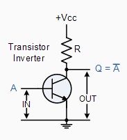
First I saw the Not Gate here: Logic "NOT" Gates where you can find a lot of information about different types of logic gates and specifically inverters. There I saw the following diagram:

not gate diagram

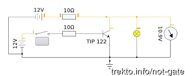
With KTechLab I made this circuit diagram:

not gate circuit diagram

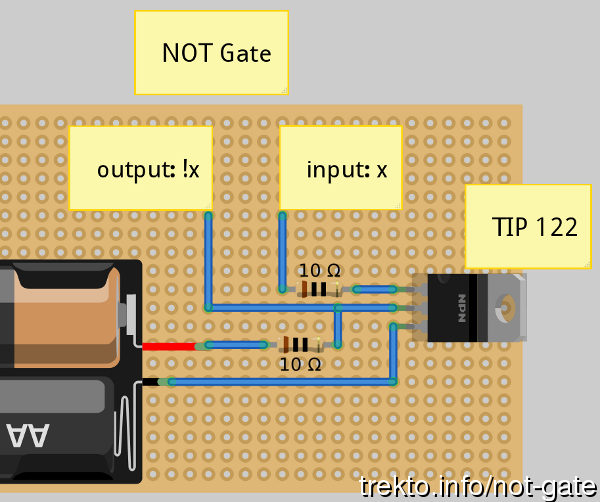
With Fritzing I made this scheme:

not gate scheme

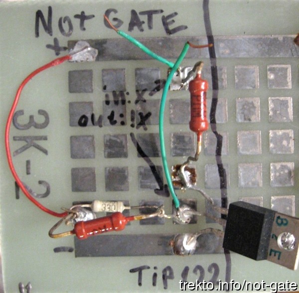
And finally my implementation of the Not gate:

digital inverter implementation

Hope this is usefull.

Коментари

Публикувай нов коментар

  • Адресите на уеб-страници и e-mail адресите автоматично се конвертират в хипервръзки.
  • Разрешени HTML tag-ове: <a> <p> <span> <div> <h1> <h2> <h3> <h4> <h5> <h6> <img> <map> <area> <hr> <br> <br /> <ul> <ol> <li> <dl> <dt> <dd> <table> <tr> <td> <em> <b> <u> <i> <strong><font> <del> <ins> <sub> <sup> <quote> <blockquote> <pre> <address> <code> <cite> <embed> <object> <param> <strike> <caption>
  • Линиите и параграфите се прекъсват автоматично.
  • Mark language-dependent sections with == lc == where lc (or lc-xx) is a language code, other or all.

Повече информация за опциите на форматиране

CAPTCHA
11 + 0 =
Solve this simple math problem and enter the result. E.g. for 1+3, enter 4.